How Does a Brushless Motor Work? — Working Principle, Structure & Control Explained.
This guide explains how a brushless DC (BLDC) motor works — from the physical structure (stator, rotor, Hall sensors) through 3-phase electronic commutation to controller types (six-step vs FOC) and gearbox pairing. Written for engineers and procurement teams evaluating brushless motors for industrial projects.
Author: Shenghe Motor Engineering Team · Published 2026-06-01
1. Brushed vs Brushless — The Core Difference
To understand how a brushless motor works, start with what it eliminates: carbon brushes.
A conventional brushed DC motor uses carbon brushes that physically press against a rotating commutator to switch current direction in the rotor windings. This mechanical contact creates friction, wear, heat, electrical noise and dust — all of which limit the motor's speed, efficiency and service life.
A brushless DC motor (BLDC motor) flips the architecture:
- Rotor: carries permanent magnets (no windings, no commutator)
- Stator: carries the copper windings (three phases arranged 120° apart)
- Commutation: done electronically by a controller, not mechanically by brushes
Because there is no physical contact between moving and stationary parts (other than the bearings), a brushless motor lasts longer, runs quieter and wastes less energy as heat.
Brushed vs Brushless DC Motor — Key Differences
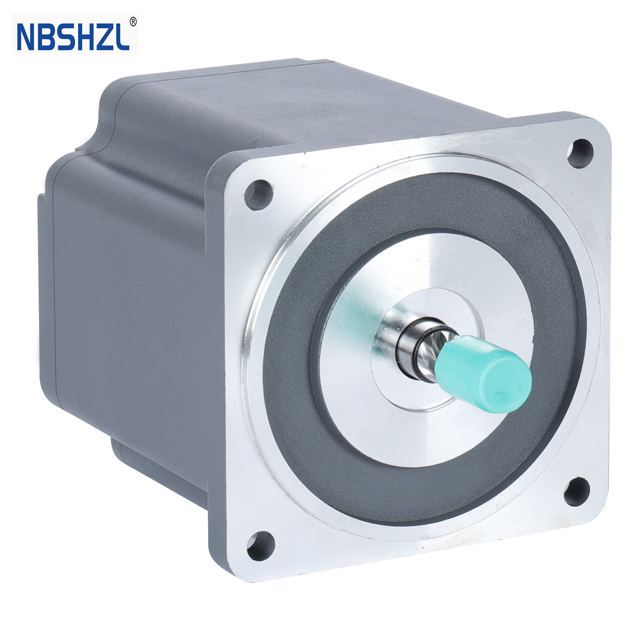
2. BLDC Motor Structure — Stator, Rotor, Hall Sensors
A brushless DC motor has three main components:
Stator (stationary part)
The stator is the outer part of the motor, containing three sets of copper windings (called phases A, B and C) wound around laminated steel cores. The three phases are arranged 120° electrical apart. When current flows through a phase, it creates a magnetic field — the controller switches current between phases to create a rotating magnetic field that pulls the rotor around.
Rotor (rotating part)
The rotor sits inside the stator (in the "inner rotor" design used in most industrial BLDC motors). It carries high-energy permanent magnets — typically neodymium (NdFeB) — arranged in alternating north-south pole pairs. Common configurations are 4-pole, 8-pole or 10-pole. Higher pole counts produce more torque at lower speed but reduce maximum RPM.
Hall sensors (position feedback)
Three Hall-effect sensors are mounted on the stator at 120° electrical spacing. They detect the magnetic polarity of the passing rotor magnets and output digital high/low signals. These signals tell the controller which rotor sector is currently aligned, so it can energize the correct stator winding pair at the right moment. This is how electronic commutation replaces mechanical brushes.
BLDC Motor Cross-Section — Stator, Rotor & Hall Sensors

3. How 3-Phase Commutation Works
This is the core of how a brushless motor works. The controller reads the three Hall sensor signals and decides which two of the three stator phases to energize at any moment. This is called six-step commutation — in one full electrical revolution, the controller switches through six distinct phase-pair combinations:
| Step | Hall A | Hall B | Hall C | Phase energized | Current direction |
|---|---|---|---|---|---|
| 1 | 1 | 0 | 0 | A → B | A high, B low |
| 2 | 1 | 1 | 0 | A → C | A high, C low |
| 3 | 0 | 1 | 0 | B → C | B high, C low |
| 4 | 0 | 1 | 1 | B → A | B high, A low |
| 5 | 0 | 0 | 1 | C → A | C high, A low |
| 6 | 1 | 0 | 1 | C → B | C high, B low |
At each step, one phase is driven high (connected to DC+), one is driven low (connected to DC−), and the third phase floats (disconnected). The controller's power stage — six MOSFETs arranged as three half-bridges — does the switching. As the rotor magnets pass the Hall sensors, the sensor states change, and the controller advances to the next step. This creates the rotating magnetic field that pulls the rotor around continuously.
Speed control is achieved by adjusting the voltage or PWM duty cycle applied to the active phases. Higher duty cycle → more current → stronger magnetic field → more torque and higher speed (up to the rated limit).
For a detailed view of the MOSFET inverter topology and the commutation timing diagram, see our BLDC Motor Diagram article.
4. Controller Types — Six-Step vs FOC
The controller is what makes a brushless motor actually run. Two main control strategies exist:
Six-step trapezoidal commutation
- Energizes two phases at a time, switching every 60° electrical
- Uses Hall sensors for rotor position (no encoder needed)
- Simple, low-cost controller — sufficient for most industrial drives
- Produces some torque ripple at each switching point — acceptable for pumps, fans, conveyors, AGVs
FOC (Field-Oriented Control) / sinusoidal commutation
- Energizes all three phases simultaneously with sinusoidal current waveforms
- Uses an incremental encoder for precise rotor angle feedback
- Real-time current control in a rotating d-q reference frame
- Much smoother torque — preferred for servo, robotics, CNC and precision positioning
- Higher controller cost and complexity
| Attribute | Six-Step | FOC |
|---|---|---|
| Position sensor | 3× Hall sensors | Incremental encoder |
| Torque ripple | Moderate (6× electrical freq) | Very low |
| Acoustic noise | Audible at low speed | Very quiet |
| Speed accuracy | ±3–5% | ±0.1% (with encoder) |
| Controller cost | Low | Medium–High |
| Best for | Pump, fan, conveyor, AGV | Servo, robotics, CNC, medical |
Shenghe manufactures both six-step controllers (BLD22010, BLD6010 series) and FOC servo controllers (BLDB6010) in-house, so we can supply matched motor + controller packages. See BLDC Motor Controller for details.
Looking for a Brushless Motor for Your Project?
Shenghe Motor manufactures 3-phase BLDC motors from 30W to 2000W with matched gearboxes and controllers. Tell us your requirements — we will recommend a build and send a datasheet within 24 hours.
Manufacturer, Not Reseller.
Shenghe Motor owns the factory in Cixi, Ningbo — CNC machining, stator winding, rotor assembly, controller PCB production and end-of-line testing all in-house. ISO 9001 certified. We design and build brushless DC motors, not resell them.
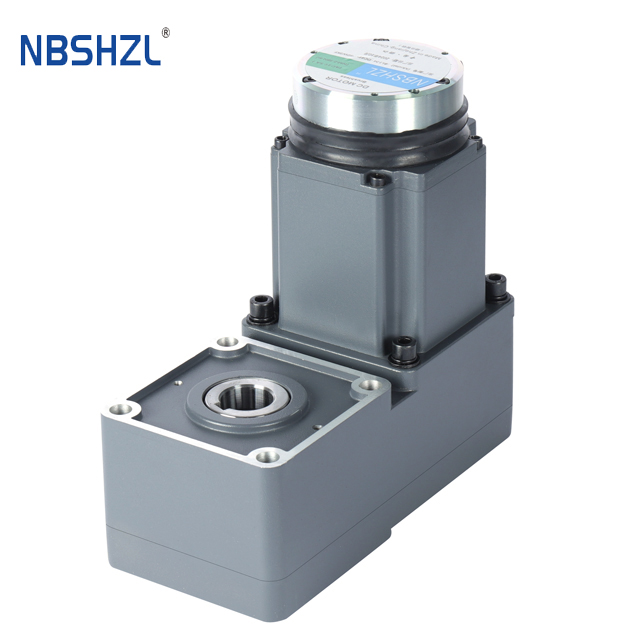
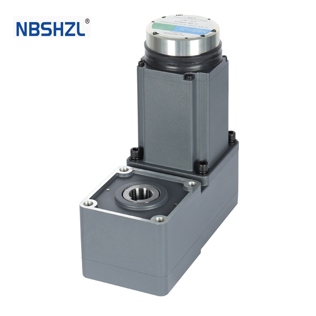
About Shenghe Motor →5. Speed and Torque — How Gearboxes Extend Capability
A brushless motor's speed is determined by the supply voltage and the motor's KV constant (RPM per volt). Industrial BLDC motors typically run at 3000–5000 RPM rated speed. But many applications need much lower output speed with much higher torque — this is where a gearbox comes in.
A gearbox converts high motor RPM into lower output RPM while multiplying torque proportionally (minus efficiency losses). For example:
- A 3000 RPM motor with a 50:1 planetary gearbox → 60 RPM output at ~48× the motor's torque
- A 4000 RPM motor with a 100:1 worm gearbox → 40 RPM output with self-locking capability
Running the motor at its high rated RPM and reducing speed at the gearbox is more efficient than winding the motor for low speed directly. This is why most industrial BLDC installations are actually geared BLDC motors — motor + gearbox supplied as one tested unit.
Shenghe pairs BLDC motors with three gearbox families:
| Gearbox type | Ratios | Strength | Best for |
|---|---|---|---|
| Planetary | 3:1 – 500:1 | Highest torque density, compact, low backlash | AGV, conveyor, robotics |
| Worm | 10:1 – 100:1 | Self-locking, very high ratio in one stage | Lifting, positioning, doors |
| Right-angle | 3:1 – 100:1 | 90° output, space-saving | Tight installations, solar trackers |
See Geared BLDC Motor for the full product range, or High Torque BLDC Motor for applications requiring up to 300 N·m output.
6. Advantages of Brushless Motors
| Advantage | Why it matters |
|---|---|
| Long service life (20,000+ hours) | No brush wear — only bearings degrade over time |
| High efficiency (85–92%) | No brush friction or commutator sparking losses |
| Low noise | No brush contact noise — important for indoor, medical, lab applications |
| Low EMI | No sparking at the commutator — easier to pass EMC compliance |
| High speed capability | No brush bounce or wear at high RPM — see High Speed BLDC Motor |
| Precise speed/torque control | Electronic commutation allows closed-loop control via encoder |
| Compact power density | More power per unit volume vs equivalent brushed motor |
| Low maintenance | No brush replacement schedule — critical for hard-to-access installations |
7. Industrial Applications
Brushless DC motors are used wherever efficiency, longevity and controllability matter more than the initial cost of the controller. Common industrial applications include:
| Application | Why BLDC | Typical config |
|---|---|---|
| AGV / AMR traction | High torque, low noise, long duty cycle | 48V/72V + planetary gearbox |
| Conveyor drives | Precise speed control, low maintenance | 24V/48V + worm or planetary gearbox |
| Pump & fan | Continuous high-RPM, quiet operation | 24V/48V bare motor or low-ratio gear |
| Robotics & cobots | Smooth torque (FOC), compact size | 24V + planetary gearbox + encoder |
| Medical equipment | Low noise, low EMI, sterilizable | 12V/24V small frame + planetary gear |
| Packaging machinery | High duty cycle, precise positioning | 48V + encoder + FOC controller |
| Solar tracker | Low-speed high-torque, outdoor IP65 | 24V/48V + worm or right-angle gearbox |
| Electric vehicle / e-rickshaw | High power, regenerative braking | 48V/60V/72V + controller package |
Browse application-specific pages: AGV · Conveyor · Pump · Drone · Elevator · Wheelchair
8. Frequently Asked Questions
How does a brushless motor work?
A brushless motor works by using electronic commutation instead of mechanical carbon brushes. Three sets of stator windings (arranged 120° apart) are energized in sequence by a controller based on rotor position feedback from Hall sensors. The permanent-magnet rotor follows the rotating magnetic field produced by the stator, creating continuous rotation. Because there is no physical brush-to-commutator contact, brushless motors have longer service life, lower noise, higher efficiency and less maintenance than brushed DC motors.
What is the difference between a brushless motor and a brushed motor?
A brushed DC motor uses carbon brushes pressing against a mechanical commutator to switch current direction in the rotor windings. A brushless DC motor eliminates brushes entirely — the rotor carries permanent magnets and the stator carries the windings, and an electronic controller switches the stator current based on rotor position from Hall sensors. The result: brushless motors last longer (no brush wear), run quieter, produce less EMI, are more efficient (85–92% vs 70–80%) and can operate at higher speeds. The trade-off is that brushless motors require an electronic controller (driver), while brushed motors can run from a simple DC power supply.
What are Hall sensors in a brushless motor?
Hall sensors are small semiconductor devices mounted on the stator (typically three sensors at 120° electrical spacing) that detect the magnetic field of the rotating permanent-magnet rotor. They output digital high/low signals that tell the controller which rotor sector is currently aligned with which stator winding — the controller uses this information to energize the correct pair of windings at the right time. Three Hall sensors produce six unique state combinations per electrical revolution, matching the six commutation steps of a 3-phase BLDC motor.
Can a brushless motor run without a controller?
No. A brushless DC motor cannot run by simply connecting it to a DC power supply — it requires an electronic controller (also called a driver or ESC) to commutate the stator windings in the correct sequence. The controller reads rotor position from Hall sensors (or estimates it from back-EMF in sensorless mode) and switches current through the three phase windings accordingly. Without a controller, the stator field would be static and the rotor would not rotate continuously.
What is the difference between six-step commutation and FOC?
Six-step (trapezoidal) commutation energizes two of the three phases at a time, switching the active pair every 60° electrical based on Hall sensor feedback. It is simple, robust and low-cost but produces torque ripple at each switching point. FOC (Field-Oriented Control) energizes all three phases simultaneously with sinusoidal current waveforms, using an encoder for precise rotor angle feedback and real-time current control in a rotating reference frame (d-q axis). FOC produces smoother torque, lower noise and better dynamic response — preferred for servo, robotics and precision applications — but requires a more capable controller and an encoder.
Why are brushless motors more efficient than brushed motors?
Brushless motors are more efficient for three reasons: (1) no brush friction — carbon brushes rubbing against the commutator waste energy as heat; (2) lower copper loss — the stator winding design in BLDC motors allows better copper utilization; (3) no commutator sparking — brushed motor sparking wastes energy and generates EMI. Industrial BLDC motors typically achieve 85–92% efficiency compared to 70–80% for equivalent brushed DC motors.
Continue Learning
Tell Us Your Application Requirements.
Provide voltage, power, speed, torque, load type and application — we will recommend a matched BLDC motor build.