
Engineering Reference Engineering: salesexp@nbshzl-motor.com
Engineering Reference — Same Product, Academic Terminology

Epicyclic Gear Motor — Planetary Reduction Drive Engineering Reference & Catalog.

"Epicyclic" is the British / European engineering term for what the American gear industry calls "planetary". DIN 868 defines epicyclic gear terminology; BSI engineers, ISO standards committees, and most European mechanical engineering textbooks (Childs, Stachowiak, Niemann) use the epicyclic vocabulary throughout. This page is written for engineers and procurement teams who learned mechanical engineering in that tradition — full kinematic reference (Willis equation, contact ratio, module-based gear notation) plus the Shenghe catalog matched to academic spec conventions.

  • Same physical product as /planetary-gear-motor/ — different terminology, identical hardware
  • Voltage 12V to 72V DC; reduction ratio 3:1 to 500:1; output torque 0.5 to 300 N·m
  • AGMA Q9-Q11 (DIN 7/8) standard; Q12 (DIN 6) ground gears on request for <5 arc-min backlash
  • Gear module m = 0.5 to 4 mm, pressure angle α = 20° per DIN 867, contact ratio ε ≥ 1.6 spur / ≥ 2.2 helical
  • Manufactured in Cixi (Ningbo), ISO 9001 / CE EMC + LVD / RoHS certified
DIN 868 / AGMA 6123 Compliant
20CrMnTi Case-Hardened HRC 58-62
GCr15 / SUJ2 Bearings P5 / P6
Module m = 0.5-4 mm 20° Pressure Angle
Cixi (Ningbo) Factory + Audit Welcome
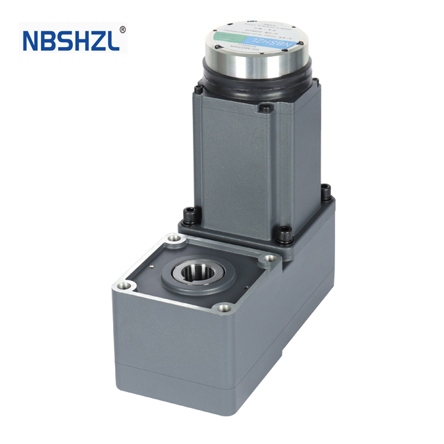
Shenghe epicyclic gear motor — sun gear + 3 planet gears + ring gear assembly paired with brushless DC motor, output flange visible on the carrier side.
Single-stage epicyclic gear train: central sun gear drives 3 planet gears constrained by the outer ring gear; output taken from the planet carrier.
Nomenclature First — Then The Catalog

Sun, Planets, Carrier, Ring — The Four Elements That Make An Epicyclic Train.

Every epicyclic gear train consists of the same four elements: a central sun gear; three (or sometimes five) planet gears that orbit the sun while spinning on their own axes; a planet carrier that constrains the planets at their orbital positions and provides the output shaft; and an outer ring gear (also called the annulus) with internal teeth. To convert the system to a single-degree-of-freedom reduction drive, one of these four elements must be held fixed — in the standard configuration used in industrial gear motors, the ring is fixed to the housing, the sun is the input, and the carrier is the output.

  • Sun gear (Greek-derived from the central celestial body): the central pinion driven by the motor shaft. Tooth count Z_sun typically 12-30 teeth.
  • Planet gears: 3 (sometimes 5) identical gears orbiting the sun. Each planet meshes externally with the sun and internally with the ring. Tooth count Z_planet typically 14-40 teeth.
  • Planet carrier: rigid plate holding the planet pins at fixed radial positions; provides the output shaft.
  • Ring gear / annulus: internal-toothed outer gear, fixed to the housing. Tooth count Z_ring = Z_sun + 2·Z_planet (geometric constraint).
Kinematics — The Willis Equation

How To Derive The Reduction Ratio.

For the standard fixed-ring configuration (ring stationary, sun as input, carrier as output), the kinematic ratio comes from the Willis equation applied with ω_ring = 0:

i = ω_sun / ω_carrier = 1 + Z_ring / Z_sun

Worked example. Z_sun = 18 teeth, Z_planet = 27 teeth. Geometric constraint: Z_ring = 18 + 2 × 27 = 72 teeth. Ratio i = 1 + 72/18 = 5:1 single-stage.

The same epicyclic train can be operated with different fixed elements to give different ratios — this is what makes the configuration useful in automotive automatic transmissions and hybrid powertrains:

Configuration Fixed Input Output Kinematic ratio (Z_sun=18, Z_ring=72)
Standard reduction Ring Sun Carrier i = 1 + Z_ring/Z_sun = 5:1
Reduction (alternate) Sun Ring Carrier i = 1 + Z_sun/Z_ring = 1.25:1
Speed increase / overdrive Ring Carrier Sun i = Z_sun/(Z_sun + Z_ring) = 0.20:1 (i.e., 5:1 step-up)
Reverse direction Carrier Sun Ring i = -Z_ring/Z_sun = -4:1 (reversed)
Differential (no element fixed) None (2 inputs) Sun + Ring Carrier ω_carrier = (Z_sun·ω_sun + Z_ring·ω_ring) / (Z_sun + Z_ring)

Shenghe industrial catalog focuses on the standard fixed-ring reduction (top row). Differential and overdrive configurations available as ODM with custom carrier + housing tooling for hybrid drivetrain and tool-machine spindle integration — see /odm-bldc-motor/.

Multi-Stage Compound Trains

How Higher Ratios Are Built — Series-Stacked Simple Stages.

A single epicyclic stage practically tops out around 10:1 (limited by the geometric constraint Z_ring = Z_sun + 2·Z_planet and the minimum-tooth-count rule of thumb Z_sun ≥ 12 to avoid undercutting). Higher ratios are built by stacking simple stages in series — the carrier output of stage N becomes the sun input of stage N+1. Total ratio is the product:

i_total = i_1 × i_2 × i_3 × ... × i_n

Stages Typical stage ratios Total ratio range Backlash (Q9-Q11) Combined efficiency
1-stage simple epicyclic 3:1, 4:1, 5:1, 6:1, 8:1, 10:1 3:1 to 10:1 5-10 arc-min ~94%
2-stage compound e.g. 5:1 × 4:1 = 20:1 12:1 to 100:1 10-20 arc-min ~88%
3-stage compound e.g. 5:1 × 5:1 × 5:1 = 125:1 125:1 to 500:1 15-30 arc-min ~82%
4+ stages (custom) e.g. 5:1 × 5:1 × 5:1 × 5:1 = 625:1 500:1 to 10,000:1 (ODM) 20-40 arc-min ~77%

Compound vs Wolfrom configuration: the standard multi-stage approach (above) stacks simple stages in series. The Wolfrom epicyclic train uses a single compound stage with two coupled ring gears and stepped planet gears, achieving 30:1 to 250:1 in a single axial envelope — used in robotics joints and aerospace actuators where axial length matters. Shenghe quotes Wolfrom builds as ODM with new gear-hob tooling for projects with strict axial constraints.

Gear Tooth Geometry & Standards

Module-Based Gear Notation Used Throughout The Catalog.

Shenghe epicyclic gear motors specify gear geometry in metric module notation per DIN 867, the European standard for involute gear tooth profiles. The catalog references the following parameters:

Parameter Symbol Shenghe spec range Standard reference
Module (metric) m 0.5 to 4 mm; small frames (22-42 mm) use m = 0.5-1.5; medium (57-86 mm) m = 1.5-2.5; heavy (115 mm) m = 2-4 DIN 867 / ISO 53
Pressure angle α 20° standard; 14.5° / 25° available on ODM tooling DIN 867
Helix angle β 0° (spur) standard; helical option β = 12°-20° on request for noise / smoothness DIN 3960
Contact ratio ε ε ≥ 1.6 typical for spur tooth profile; ε ≥ 2.2 with helical option ISO 6336-1
Quality grade AGMA Q9-Q11 standard (DIN 7/8 equivalent); Q12 (DIN 6) ground gears on request AGMA 2015 / DIN 3962
Tooth profile Involute with tip relief on planet teeth (reduces noise under load) DIN 3961
Gear material 20CrMnTi case-hardening steel, surface hardness HRC 58-62, core HRC 32-40 GB/T 3077 / DIN 17210
Heat treatment Carburised at 920-940°C, oil-quenched, low-temperature tempered at 180-200°C; case depth 0.6-1.2 mm depending on module GB/T 9450 / DIN 50190
Sun-planet centre distance a a = m × (Z_sun + Z_planet) / 2 — derived per DIN 3960 DIN 3960
Bearing accuracy class P5 / P6 for planet pins and output shaft ISO 492 / ABMA 20

Gear bending stress (Lewis equation) and Hertz contact stress at the sun-planet mesh are verified against ISO 6336-2 / -3 fatigue limits during the gear sizing pass at quote stage — full FEA + tooth-flank loading verification available on request for high-cycle applications. Material certificates (mill certs for 20CrMnTi gear steel, GCr15 bearing steel) included with audited shipments.

Load Distribution & Failure Modes

How The Load Shares Across The Planets, And What Fails First.

The 2-3× torque-density advantage of an epicyclic train over a single-mesh spur reduction comes from load sharing across N planet meshes. Ideal: each planet carries T_carrier / N_planets (typically 3 planets, sometimes 5 in high-torque-density custom builds). In practice, manufacturing tolerances cause 10-20% load imbalance.

Failure mode Mechanism Mitigation
Planet-tooth pitting at the most-loaded mesh Hertz contact fatigue at the gear flank under repeated rolling-sliding contact; surface micro-cracks coalesce into pits 20CrMnTi case-hardened to HRC 58-62 (resists Hertz pitting); Q12 ground tooth profile (lower stress concentration); floating sun design to equalise planet load
Planet bearing brinelling or pitting Radial load on planet pin + planet's orbital motion drives bearing fatigue; concentrated load on the most-loaded planet's pin bearing GCr15 / SUJ2 bearing steel through-hardened to HRC 60-65; P5/P6 accuracy class; lithium-complex grease NLGI 2 sealed-for-life from factory
Sun-gear tip wear Sliding contact at gear engagement / disengagement (relative sliding peaks at tip of driving tooth); thin oil film at light loads Tip relief on planet teeth (shifts contact away from sun-tooth tip); ISO VG 220 EP grease additive on heavy-duty applications; surface treatment (PVD or DLC) for ODM high-cycle applications
Ring-gear / housing fretting Press-fit interface between ring gear and housing micro-slips under thermal cycling; fretting wear at the interface drives ring radial growth Loctite 638 retainer at the press-fit interface; thermal expansion matched between housing (cast Al ADC12 or 45 steel) and ring (20CrMnTi steel); heavy frames use steel housing to match
Carrier compliance under load Carrier plate deflects under reaction torque; planets tilt; planet-pin alignment skews; load redistributes unfavourably Floating-sun design: sun gear free to translate radially within input bearing clearance; sun finds the equilibrium position where the three planets share load equally
Oil-seal degradation at output shaft NBR seal lip thermal aging under continuous duty; eventual oil seepage NBR standard for IP54; FKM (Viton) seal lip for IP65 / high-temperature applications; double-lip seal on heavy frames

MTBF projection methodology: bearing-limited L10 life calculated per ISO 281 from the most-loaded planet's bearing load + duty cycle. Gear-tooth fatigue life calculated per ISO 6336-6 from Hertz contact stress + bending stress + load cycles. Both projections returned at quote stage for the specific SKU + duty cycle. No fabricated fleet-average MTBF numbers — projections are bench-test + load-spectrum based and conservative.

Shenghe Epicyclic Catalog

Voltage / Power / Frame / Ratio Matrix.

The Shenghe epicyclic gear motor catalog matches what the planetary catalog covers — voltage, motor frame, and ratio bands. Detailed catalog browse and ordering happens on the voltage-specific SKU pages linked in the table.

Voltage Power band Motor frame Ratio range Output torque SKU page
12V DC 10-200 W 22-42 mm 3:1 to 100:1 0.5-15 N·m 12V BLDC Planetary / Epicyclic →
24V DC 50-500 W 42-57 mm 3:1 to 200:1 2-60 N·m 24V BLDC Planetary / Epicyclic →
36V DC 250-800 W 57-86 mm 3:1 to 200:1 8-100 N·m BLDC Planetary (Master) →
48V DC 500-1,500 W 57-115 mm 3:1 to 500:1 15-280 N·m 48V BLDC Planetary / Epicyclic →
72V DC 1,000-3,000 W 86-115 mm 3:1 to 500:1 30-300 N·m BLDC Planetary (Master) →

For brushed-DC + brushless-DC combined catalog covering the same product family, see /dc-planetary-gear-motor/ — also written for the same hardware under the "DC planetary" framing covering both motor commutation types.

FAQ — Engineering Vocabulary

What Engineers Trained In The European Tradition Ask.

Is "epicyclic gear motor" the same product as "planetary gear motor"?
Yes — same physical hardware, different terminology tradition. "Epicyclic" is the British / European academic and standards term (BSI, ISO, DIN 868, European textbooks: Shigley, Norton, Childs, Niemann). "Planetary" is the American commercial term (Boston Gear, Bodine, Maxon catalogues). Shenghe manufactures the same gear motors at Cixi, Ningbo and quotes either way.
What's the standard reduction-ratio equation for a fixed-ring epicyclic?
i = 1 + Z_ring / Z_sun, where Z_ring is the ring gear tooth count and Z_sun is the sun gear tooth count. The Willis equation in its most-used form. Geometric constraint Z_ring = Z_sun + 2·Z_planet must hold.
Simple, compound, differential — what's the practical difference?
Simple: one set of sun + planets + ring, one fixed element. Standard industrial reduction. Compound: simple stages stacked in series for higher ratio (Shenghe 2-stage and 3-stage builds). Wolfrom: single compound stage with two coupled rings for high ratio in compact axial envelope. Differential: two inputs, one output — used in automotive differentials and hybrid powertrains (Toyota Prius), not standard in industrial gear motors.
How does epicyclic backlash compare to spur train backlash?
5-10 arc-min epicyclic single-stage vs 30-60 arc-min spur train at comparable reduction. Load sharing across 3 planets means the worst-case planet's backlash dominates (not the sum). Q12 ground gears drop epicyclic backlash below 5 arc-min single-stage; below 1 arc-min, harmonic drive becomes the right answer instead.
What module and contact ratio do Shenghe catalog gears use?
Module m = 0.5 to 4 mm depending on frame size, DIN 867 20° pressure angle. Contact ratio ε ≥ 1.6 spur / ≥ 2.2 with helical β = 12°-20° option. Custom module outside 0.5-4 mm or alternative pressure angles (14.5° / 25°) available as ODM with new gear-hob tooling.
How are sun-planet load imbalance and carrier compliance handled?
Floating-sun design: sun gear free to translate radially within input bearing clearance, finds equilibrium position where 3 planets share load equally within 10-20% imbalance. Q12 ground gears reduce stress concentration on the most-loaded planet. GCr15 / SUJ2 planet-pin bearings with P5 / P6 accuracy class limit pin position scatter.
Epicyclic vs harmonic drive — when does each win?
Epicyclic: higher stiffness, higher load capacity, ratio 3:1 to 500:1 per stage, backlash 5-30 arc-min standard / <5 arc-min Q12 ground, efficiency 82-94% per stage. AGV / lift / packaging / valve actuator / industrial automation. Harmonic drive: near-zero backlash <1 arc-min, ratio 30:1 to 320:1 per stage, lower stiffness + lower load + lower efficiency 70-90%. Collaborative robot joints / semiconductor wafer handling / surgical robotics. Shenghe focuses on epicyclic; quotes harmonic-drive integration through partners for projects that require it.
How is MTBF projected — fleet-average or bench-test?
Bench-test + load-spectrum based, not fleet-average. Bearing L10 life per ISO 281 from most-loaded planet's bearing load × duty cycle. Gear-tooth fatigue per ISO 6336-6 from Hertz contact stress + bending stress + load cycles. Returned at quote stage for the specific SKU + duty cycle.
Quote & Selection

Quote & Engineering Sizing.

For SKU selection, voltage / power / ratio matching, and the dyno-validated quote, the engineering inquiry form lives on the parent Planetary Gear Motor page — same product, full form widget hosted there to avoid duplicating the inquiry workflow.

If your project requires specifically epicyclic-tradition documentation (DIN 868 nomenclature, ISO 6336 fatigue verification, module-notation drawings, Willis-equation kinematic charts), note that in the inquiry message and engineering will return the deliverables in academic notation.

For AGV-specific drive integration (motor + gearbox + controller sizing with worked examples), see /agv-drive-system/ — full engineering reference page with 5-step sizing methodology and real reference deployment.