Engineering Reference Engineering: salesexp@nbshzl-motor.com
Engineering Reference — Not A Procurement Brochure

AGV Drive System Design — BLDC + Gearbox + Controller Engineering Reference.

This page is written for the hardware / mechatronics / mechanical engineer specifying the drive system for an AGV, AMR or material handling transfer cart. The decision is the same on every project — pick the motor, pick the gearbox ratio, pick the controller, validate the integration on the bench. The four sections below cover the engineering: payload-class configuration table, sizing methodology (with formulas), communication protocols, and a real reference deployment with a Turkish automotive-supply-chain integrator. Engineering Pack (torque-speed curves, 3D STEP, wiring diagrams, controller protocol manual) requested via the form below and emailed within one business day.

  • Four AGV payload classes — light <100 kg / medium 100–500 kg / heavy 500–3,000 kg / heavy-load transfer cart 3–60 ton
  • Recommended SKU configurations per class — real Shenghe motor + gearbox + controller combinations
  • 5-step sizing methodology with formulas and worked examples
  • RS232 / RS485 Modbus RTU native; CANopen on BLDB6010 servo; CAN bus variant on BLD6010 firmware
  • Reference deployment — Turkish Tier-1 automotive-supply-chain EPC integrator (anonymized)
50-Person Cixi (Ningbo) Factory
ISO 9001 + CE EMC + LVD + RoHS
Per-Unit Dyno Test Record
Modbus / CANopen Native Protocols
1 Business Day Engineering Pack Response
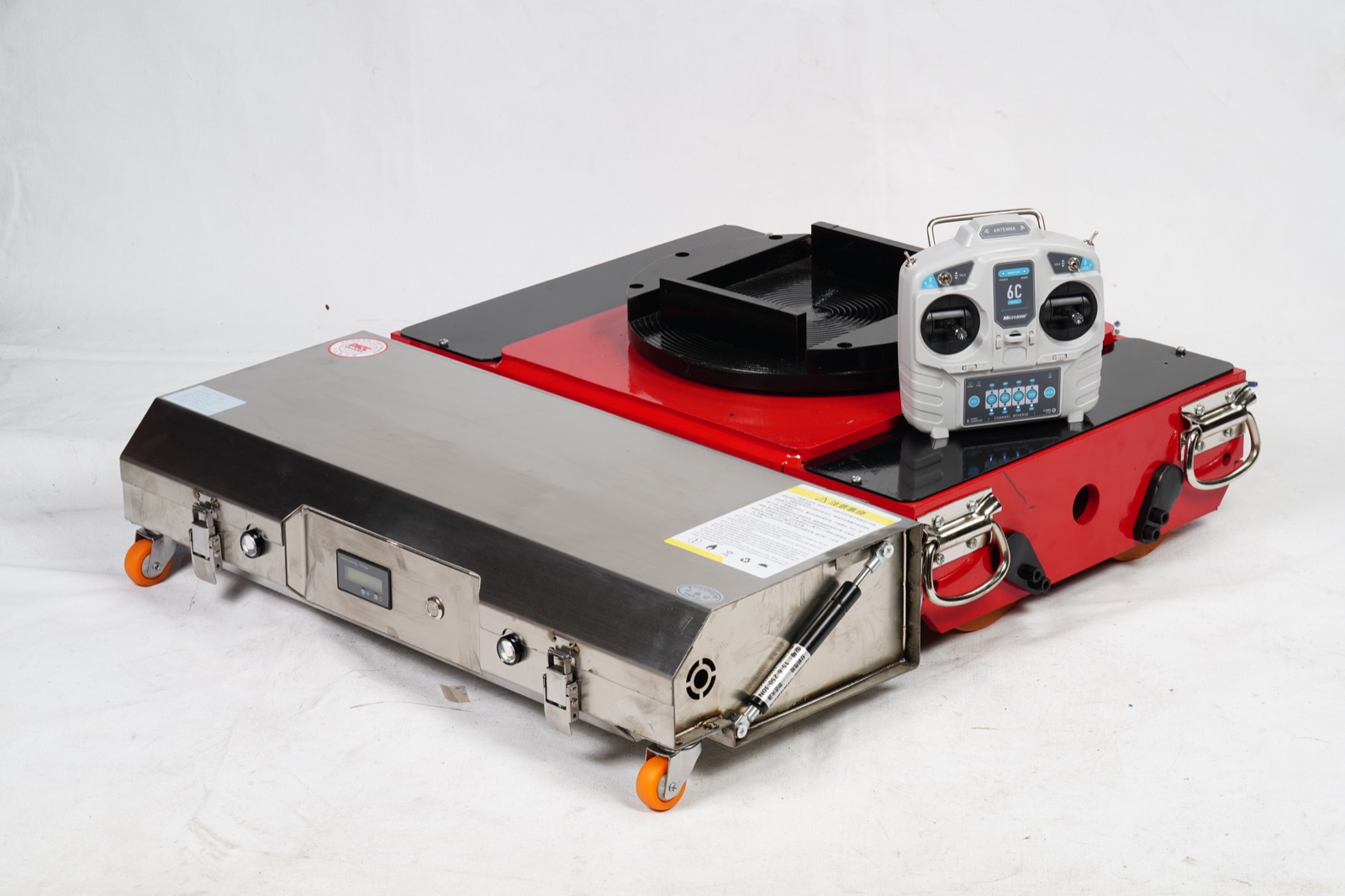
Shenghe AGV drive system — 48V BLDC motor + 2-stage planetary gearbox + matched BLD6010 controller + D003 wireless remote, integrated transfer cart application.
Integrated Shenghe AGV drive — 48V BLDC traction motor + planetary gearbox + BLD6010 controller + D003 wireless remote on a heavy-load transfer cart application.
What This Page Replaces

One Page Of Spec — Not Eight Pages Of Marketing.

The procurement-facing product pages (/electric-tank-carrier/, /heavy-duty-agv/, /agv-tractor/ and others) cover SKUs and the buyer-facing decision. This page goes one level deeper — the integration-side decision: what does the engineer building the AGV need to verify before signing the BOM.

  • Configuration tables map payload class → motor SKU + gearbox stage + controller part number — start with the row that matches your AGV class
  • Sizing methodology section has the formulas + two worked examples (200 kg AMR @ 1.5 m/s, 1,200 kg transfer cart @ 0.5 m/s)
  • Engineering Pack section requests torque-speed curves, 3D STEP CAD files, wiring schematics, and the BLD-series RS485 register map — emailed within one business day
  • Reference deployment section documents a real customer integration — anonymized but real spec
AGV Payload Class Navigator

Recommended Drive Configurations By AGV Class.

Pick the row that matches your AGV class — each row references real Shenghe motor + gearbox + controller SKUs. Numbers are starting points; final selection validated against your specific duty cycle and gradient via the sizing methodology in the next section.

AGV class Payload Travel speed Voltage Motor + gearbox Controller Operator interface
Light AMR (goods-to-person) <100 kg 1.5–2.0 m/s 24V DC 42 mm BLDC 100–300 W + 2-stage planetary 10:1–25:1 BLD22010 (18–60V/10A) Host PC over RS485 Modbus RTU
Medium AGV (packaging / sortation) 100–500 kg 1.0–1.5 m/s 24V / 36V DC 57–86 mm BLDC 300–800 W + 2-stage planetary 20:1–50:1 BLD22010 or BLDB6010 servo for precision positioning Host PC over RS485 Modbus RTU or CANopen DS402 (servo)
Heavy AGV (manufacturing line / hospital) 500–3,000 kg 0.5–1.0 m/s 48V DC 86–115 mm BLDC 1–2 kW + 2-stage planetary 30:1–80:1, or 3-stage 100:1–200:1 for lift drives BLD6010 (48–220V/25A continuous, 30A peak) Host PC + D003-2000W-DR wireless remote for commissioning
Heavy-load transfer cart (foundry / steel mill / die handling) 3,000–60,000 kg (3–60 ton) 0.3–0.5 m/s 48V DC dual-motor 2× 86–120 mm BLDC servo, 500–3,000 W each + 2-stage planetary 30:1–80:1 (104-flange or 120-flange brake gearbox) BLD6010 with dual-motor sync firmware D003-2000W-DR dual-motor wireless remote
Precision positioning / robot joint drive 24V / 48V DC 42–57 mm BLDC servo 100–800 W + 1-stage or 2-stage Q12 ground planetary (<5 arc-min backlash) BLDB6010 servo (24–80V FOC, 8A continuous, 17-bit absolute encoder option) Host CANopen DS402 (position / velocity / torque modes)

Sourcing: integrated kits ship as one PO — motor + gearbox + controller + remote tested together on the dyno bench before shipment, no field-tuning required. See /brushless-gearbox/ for the integration boundary detail and the three named failure modes that single-source factory eliminates.

Sizing Methodology — 5 Steps With Formulas

How To Size A BLDC Drive System For Your AGV.

The five-step methodology below is what Shenghe engineering uses when responding to a sizing inquiry. Run it yourself before requesting a quote to verify the recommendation matches your expectations.

Step 1 — Compute Wheel Torque

T_wheel = m × g × (μ_rolling × cos(θ) + sin(θ)) × r_wheel × n_drive × safety_factor

  • m = total mass: payload + AGV chassis (kg)
  • g = 9.81 m/s²
  • μ_rolling = rolling friction coefficient. Typical: 0.015 polyurethane wheel on smooth concrete; 0.025 polyurethane on rough concrete; 0.035 polyurethane on epoxy; 0.05 polyurethane on outdoor asphalt
  • θ = max gradient angle (radians). Indoor flat: 0. Loading dock ramp: typically 3–5° (0.052–0.087 rad)
  • r_wheel = wheel radius (m)
  • n_drive = number of drive wheels (most AGV: 1 or 2; transfer cart: typically 4)
  • safety_factor = 1.5–2.0 for industrial duty cycle. Higher (2.5) for safety-critical applications (medical, food processing)

Step 2 — Compute Wheel Rotational Speed

ω_wheel = v_max / r_wheel
RPM_wheel = ω_wheel × 60 / (2π)

Typical max travel speeds: 0.3–0.5 m/s heavy transfer cart; 0.5–1.0 m/s heavy AGV; 1.0–1.5 m/s medium AGV; 1.5–2.0 m/s light AMR. Faster than 2.0 m/s indoor is rare — safety considerations dominate.

Step 3 — Pick Gearbox Reduction Ratio

i_gearbox = RPM_motor_target / RPM_wheel

  • Shenghe BLDC no-load RPM: 2,000–4,000 RPM depending on frame + voltage. Under-load RPM = 60–80% of no-load.
  • Target motor under-load RPM in the 1,500–3,000 RPM band — motor efficiency peaks in this range, audible noise stays low, bearing life maximised.
  • For 200 RPM wheel target at 2,400 RPM motor → ratio 12:1. Pick 12:1 standard 2-stage planetary (efficiency ~88%).
  • Avoid ratios where motor would run >3,500 RPM under load (bearing wear) or <1,000 RPM (motor torque ripple becomes audible / felt as cogging).

Step 4 — Pick Motor Continuous Power Rating

P_continuous = T_wheel × ω_wheel / η_gearbox / η_motor

  • η_gearbox: 0.94 single-stage planetary, 0.88 two-stage, 0.82 three-stage
  • η_motor: 0.85–0.92 for BLDC at rated load and rated RPM
  • Add 30–50% headroom over the computed P_continuous for inrush, brake hold, uphill startup
  • Verify the selected SKU's continuous-duty rating (not peak rating) covers your computed P_continuous + headroom

Step 5 — Match Voltage Class And Pick Controller

Voltage class is determined by your battery system, not the motor. Pick the motor variant matching your battery voltage; then pick the controller matching the motor variant.

Voltage classPower bandMotor variantController
12V DC10–200 W22–42 mm BLDC, Hall sensorBLD22010 (18–60V/10A)
24V DC100–500 W42–57 mm BLDC, Hall sensor; servo with encoder for precisionBLD22010 or BLDB6010 servo
36V DC250–800 W57–86 mm BLDC, Hall sensorBLD22010
48V DC500–2,000 W86–115 mm BLDC, Hall sensor; servo for positioningBLD6010 (48–220V/25A continuous, 30A peak) or BLDB6010 servo
72V DC1,000–3,000 W115 mm BLDC, Hall sensor, regen-braking optionBLD6010 with regen-braking firmware variant

Worked Example 1 — 200 kg AMR @ 1.5 m/s

Assumptions: 200 kg total mass (150 kg payload + 50 kg chassis), 0.10 m wheel radius (200 mm wheel), 0.015 μ_rolling (PU on smooth concrete), 0° gradient, 2 drive wheels, 1.5× safety factor.

  • T_wheel per wheel = 200 × 9.81 × (0.015 × 1 + 0) × 0.10 / 2 × 1.5 = 2.21 N·m per wheel
  • ω_wheel = 1.5 / 0.10 = 15 rad/s → RPM_wheel = 143 RPM
  • i_gearbox = 2,500 / 143 = 17.5:1 → round to 20:1 standard 2-stage planetary
  • P_continuous per wheel = 2.21 × 15 / 0.88 / 0.88 = 42.9 W per wheel × 1.4 headroom = 60 W → pick 100 W motor
  • System: 2× 24V 100W BLDC + 2-stage planetary 20:1, BLD22010 controller per wheel

Worked Example 2 — 1,200 kg Heavy AGV @ 0.5 m/s

Assumptions: 1,200 kg total mass (1,000 kg payload + 200 kg chassis), 0.125 m wheel radius (250 mm wheel), 0.020 μ_rolling (PU on industrial floor), 0° gradient, 2 drive wheels (rear), 2.0× safety factor (heavy industrial).

  • T_wheel per wheel = 1,200 × 9.81 × 0.020 × 0.125 / 2 × 2.0 = 29.4 N·m per wheel
  • ω_wheel = 0.5 / 0.125 = 4 rad/s → RPM_wheel = 38 RPM
  • i_gearbox = 2,200 / 38 = 58:1 → round to 50:1 or 64:1 standard 2-stage planetary
  • P_continuous per wheel = 29.4 × 4 / 0.88 / 0.88 = 152 W per wheel × 1.5 headroom = 228 W → pick 400 W motor
  • System: 2× 48V 400W BLDC + 2-stage planetary 50:1, BLD6010 controller per wheel (regen-braking enabled for deceleration)

Engineering Pack

Request The Engineering Documents — Emailed Within One Business Day.

Engineering Pack documents are not hosted on this page — they're emailed direct to the requesting engineer's email after a short verification (company + project context). This keeps the BLD-series controller protocol manual + CAD files inside the OEM design boundary instead of indexed by search engines. The form below sends the request to Shenghe engineering; response within one business day with the documents matching your SKU selection.

DocumentFormatCoverage
Torque-speed curves PDF Per-SKU dyno-measured T-N curves at rated voltage. Continuous-duty + intermittent S5 envelopes shown separately. Available for every voltage × power × frame combination on this page.
3D CAD models STEP (.stp) + IGES (.igs) Top 12 BLDC + gearbox SKUs across light / medium / heavy / heavy-load classes. Includes mounting flange, output shaft, connector positions. Texture and material map omitted (CAD-only).
Wiring diagrams + Hall pinouts PDF BLDC motor phase connector (U/V/W), Hall sensor connector (5-wire), controller power input, brake resistor wiring, regen-braking option schematic, fault output signal pinouts. Per controller variant (BLD22010 / BLD6010 / BLDB6010).
BLD-series controller protocol manual PDF RS232 / RS485 Modbus RTU register map for BLD22010 and BLD6010 — full read/write register list covering speed setpoint, current limit, PID gains, fault status, encoder feedback. CANopen DS402 object dictionary for BLDB6010 servo. Includes example C / Python control snippets.
D003 wireless remote pairing guide PDF Pairing procedure for new remote-to-controller pairs, RF channel + ID configuration, multi-AGV coexistence guidance, factory reset sequence, troubleshooting (lost pairing, range issues, battery alerts).
Compliance certificates PDF ISO 9001:2015, CE EMC + LVD Declarations of Conformity, RoHS material declaration, REACH SVHC declaration, UL recognition (selected SKUs), per-unit dyno test record sample.

Note: per CLAUDE.md and engineering disclosure policy, controller firmware source and reflashing utility are released only after OEM integrator signs the firmware NDA. Distributors and confirmed-volume OEM customers (50+ unit annual commitment) get the configurator tool included with the first PO.

Reference Deployment

Reference Deployment — Turkish Tier-1 Automotive-Supply-Chain EPC Integrator.

The following deployment describes a real Shenghe customer in Sakarya, Turkey, anonymized at the customer's preference. Specs and integration model are documented as deployed.

Customer Profile

  • Industrial automation EPC integrator in Sakarya, Turkey — services automotive supply chain factories in the region
  • Customer base in their region includes the Toyota Motor Manufacturing Turkey plant (Toyota C-HR production, 5,000+ employees), Otokar (Turkish defence + commercial vehicle OEM), BMC Sakarya (truck + armoured vehicle OEM)
  • EPC service line: in-factory material handling automation, AGV / transfer-cart fleet deployment, fixture handling, line-side parts delivery

How They Found Shenghe

The integrator was originally a downstream customer of a Shenghe distributor in Turkey — buying complete Shenghe transfer carts as turnkey AGV platforms for their EPC deployments. After several months of field operation in their automotive-supply-chain factories, the engineering team opened a Shenghe transfer cart for service. The traction motor inside carried the Shenghe nameplate. They contacted Shenghe directly to source motors and matched controllers for their next platform builds — moving from distributor-supplied turnkey AGVs to direct-from-factory drive systems they integrate themselves.

This is the engineering credibility loop in practice: an integrator runs Shenghe AGVs for a year, opens one up to do bearing maintenance, sees the part nameplate, and sources direct.

Deployed Configuration

ComponentShenghe SKUSpec
Traction motor BL120-DC48V2000W3KF 120 mm BLDC, 48V DC, 2,000 W rated, brake gearbox flange (3KF). Hall sensor commutation, IP54 standard.
Controller BLD6010 DC 48–220V input, 25A continuous / 30A peak, Hall closed-loop PID, RS232 + RS485 Modbus RTU communication, overcurrent + overvoltage + short-circuit protection.
Wireless remote D003-2000W-DR Dual-motor 6-channel wireless industrial remote, 3.5" TFT screen, cruise mode + E-stop, FHSS 433 MHz, 100m line-of-sight range, factory-paired with controller pair.
Operating environment Automotive supplier factory floors, smooth concrete with epoxy coating, indoor temperature 15–35°C, single-shift 8h/day duty cycle, mixed payload 500–2,500 kg per transfer cart depending on operation.

Engineering Takeaways

  • Distributor → direct relationship transition is a normal engineering credibility milestone — integrators that touched the product first under a turnkey AGV badge convert to direct sourcing once they verify the build quality from inside the assembly.
  • BL120 + BLD6010 + D003 is the heavy-load default — 48V 2 kW class, 120 mm motor frame, 2-stage planetary brake gearbox, 25A continuous controller, dual-motor wireless remote. Documented and dyno-tested combination, no integration risk.
  • EMC immunity in automotive plants — Turkish automotive plants run mixed-source EMI environments (welding cells, conveyor drives, plasma cutting). Shenghe BLD6010 ships with IEC 61000-6-2 industrial immunity envelope verified at factory; no field EMI failures reported on this deployment after 12+ months operation.
  • Language + timezone overlap — Turkish engineering teams operate UTC+3, overlapping with Shenghe's 11 AM–6 PM working window (UTC+8). WhatsApp / WeChat technical support routes faster than email; engineering response same-day during the overlap window.

Customer identity protected at the integrator's preference. Specs, configuration and operational context are documented as deployed. Site visit / customer reference available on request after a signed mutual NDA, coordinated through Shenghe sales engineering.

FAQ For The Engineer

What Engineers Ask Before The First BOM Lock.

What's the typical MTBF on the BLDC + gearbox unit on an AGV?
18,000–25,000 operating hours bearing-limited under single-shift 8h/day S5 intermittent duty at 60% load factor. Higher under lighter duty, lower under continuous 24/7 with frequent direction-reversal. Submit your actual duty cycle to the form below for a SKU-specific MTBF projection — bench-test based, no fabricated fleet-average numbers.
Can I integrate the BLD-series controller over CAN bus?
Native: RS232 + RS485 Modbus RTU. CAN bus variant on BLD6010 as custom firmware (250 / 500 kbps tested). BLDB6010 servo supports CANopen DS402 natively — standard fleet-management integration path.
How do I size a brake resistor for regen-braking?
Rule of thumb: 30–50% of motor continuous power. For 1.5 kW AGV traction: 500 W brake resistor 50–100 Ω at 48V, mounted on a finned heatsink with thermal cutoff. Full sizing worksheet in the Engineering Pack.
What's the Hall sensor pinout?
Standard 5-wire: +5V / GND / Hall A / Hall B / Hall C. Active-low open-collector, pulled to +5V through 10 kΩ internal. 3-wire phase: U / V / W with U–V–W = CW rotation viewed from output. JST PHR housing standard; Molex Micro-Fit / Deutsch / M12 available custom.
Do you support sensorless commutation for AGV traction?
Supported but not recommended. AGV traction requires zero-RPM starting torque (uphill restart), which sensorless commutation cannot deliver — back-EMF is zero at zero RPM. Hall-sensor commutation is the default for AGV / lift / e-mobility. Sensorless suits fans, pumps, air purifiers.
What's the encoder resolution on the servo BLDC?
Incremental: 2,500–10,000 PPR quadrature → 10,000–40,000 counts/rev at motor; after 25:1 planetary → 250,000–1,000,000 counts/rev at output. Absolute: 17-bit single-turn (131,072 counts/rev) + 16-bit multi-turn option for power-cycle survival.
How do you handle thermal derating at 50°C ambient?
Standard derating curve: 80% rated current at 40°C, 65% at 50°C, 50% at 60°C. Specify thermal class F (155°C) or H (180°C) insulation as custom for 100% rated current at 50°C ambient. Forced-air / liquid cooling on 86 / 115 mm frame quoted per project.
Can I reflash the controller firmware in the field?
BLD22010 / BLD6010: field-reflashable over RS232/RS485 with Shenghe configurator (Windows .exe). BLDB6010: CANopen-based reflash with the servo configurator. Tools released after NDA — distributors and 50+ unit/year OEM customers get the configurator with first PO.
What compliance docs are available?
ISO 9001:2015, CE EMC (IEC 61000-6-2/-4) + LVD (EN 60204-1), RoHS, REACH SVHC, UL recognition (selected SKUs in 48V/72V class). Material certs (20CrMnTi / 40Cr gear steel, GCr15 bearing) on request. Per-unit dyno test record standard with every shipment.
How does the D003 wireless remote handle multi-AGV coexistence?
FHSS 433 MHz with factory-paired 16-bit unique ID. Two AGV pairs don't cross-talk at 5m range. For fleet sizes >20 AGVs in one building, migrate to centralized CANopen / Modbus TCP with SCADA / WMS interface — D003 is for commissioning + manual recovery, not fleet operation. Range: 100m line-of-sight outdoor, 30–40m through one concrete wall.
Engineering RFQ

Send The Sizing Brief — Engineering Pack + Quote Within One Business Day.

This form routes to engineering, not sales. Reply includes: SKU recommendation with rationale + computed torque margin, engineering pack documents (torque-speed curves, 3D STEP, wiring, protocol manual) matching the SKU, indicative price band. Expect technical follow-up questions before commitment.

WhatsApp Engineering